Designing a simple part

Open a new document
Start Dune 3D and create a New Document.

When done, remember to switch back to the “Sketch” group by clicking on “Sketch1”.
Sketch
Activate the “Draw contour” tool by either:
The shortcut d s
Opening the menu by pressing Space and searching for it
The topmost button on the left side of the 3D viewport
to create a sketch that looks like this:
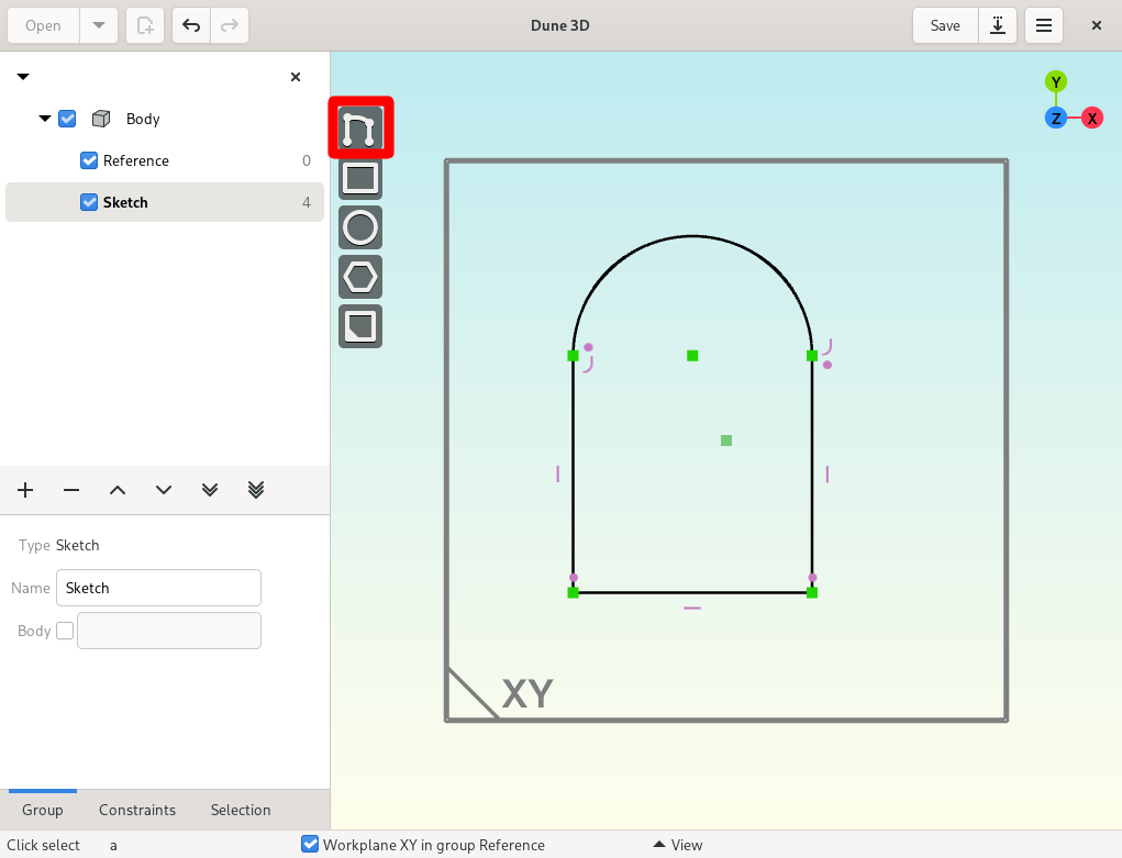
To draw the arc, press a while the tool is active.
It will automatically constrain almost-vertical/horizontal lines to be exact and creates coincident constraints when clicking on an entity.
This and other behaviour can be configured with the shortcuts listed in the bar at the bottom of the 3D viewport:

Finally, clicking on the starting point closes the path.
Note
It’s best to start from the bottom-left or bottom-right corner so that the arc/line tangential constraints get created automatically. If these didn’t get created you can add them by selecting the arc and the line leading up to it and invoking the “Constrain parallel” tool.
Constrain
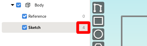
In the workspace browser on the left side, we now see that our sketch has 4 degrees of freedom. Our goal now is to get this number to zero by adding constraints.
Arc center
Constrain the center of the arc to be on the origin of the workplane.
Right-click on either of these points to open the context menu and selecting “Constrain point on point”.

This should have removed two degrees of freedom.
The added constraint is now visible in your drawing as a violet symbol above the arc’s center point:

Width
To set the width to 5mm, right-click onto the horizontal line and to invoke the constraining tool.

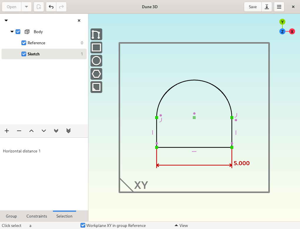
Now We should be left with only one degree of freedom.
Note
You can also just select the line and press c d h
Height
Press Space and search for “Draw point in workplane”:

and place the point on the arch.
Then use the “Constrain vertical” tool (right-click) to constrain it to be directly above the arc’s center by selecting it and the arc’s center.

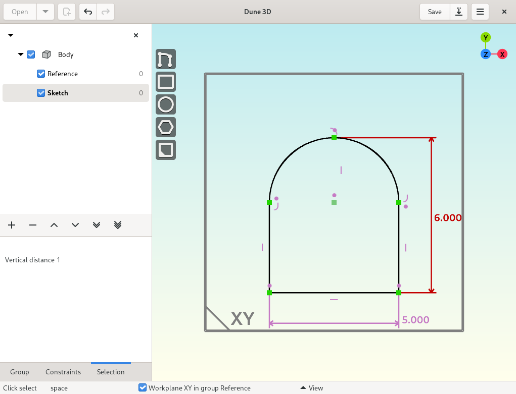
Select the point on the arc and one of the points from the bottom line and invoke (right-click) the “Constrain vertical distance” tool to set the height to 6mm.
The end result should have zero degrees of freedom and look like this:
Extrude
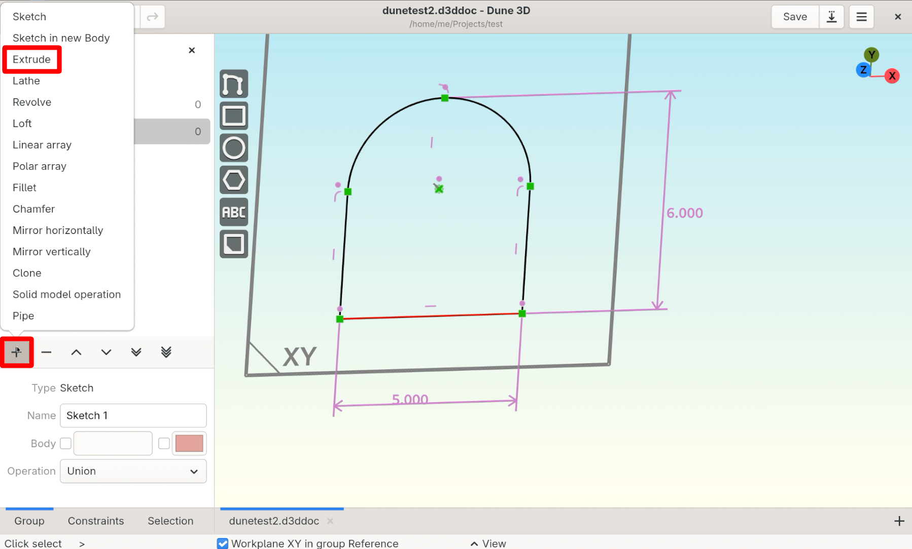
With the 2D sketch being fully constrained, let’s make it 3D.
In the workspace browser, click the plus (+) icon to add an extrusion group.
Note
See Usage for how to navigate the 3D viewport.
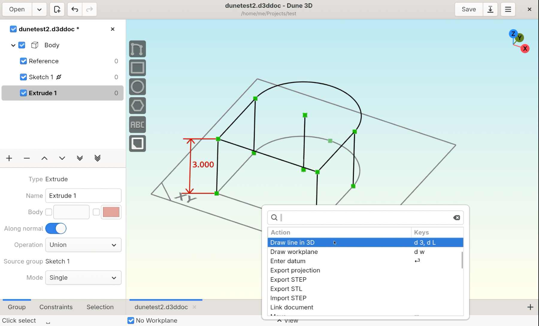
Change its height by dragging the lines on the top surface.
To set its height, right-click on one of the vertical lines and select “Constrain distance”.

Create workplane
Place a workplane at the center of the front face to create the pocket sketch.
Create a new sketch from the plus (+) icon in the workspace browser.
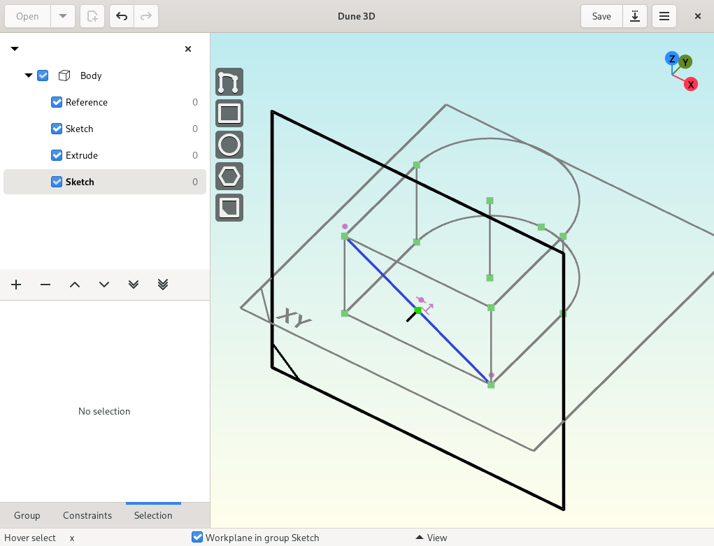
Press Space and get the “Draw Line in 3D” tool to draw a line as shown below.
Note
You can also press d 3 to get the “Draw Line in 3D” tool.
This might be is easier in wireframe view (solid model off).
Note
g toggles between construction and normal line mode.

Add the workplane with the “Draw workplane” tool.
Click on the middle of the drawn 3D line so it will automatically add the midpoint constraint so the workplane sits at the center of the face.

Watch the bottom toolbar to make sure the constraint gets created as needed.
We still need to constrain its rotation to be in plane with the face.
Use the “Constrain workplane normal” tool available when right-clicking the newly created workplane.
Note
You can also press c w to activate the “Constrain workplane normal” tool.
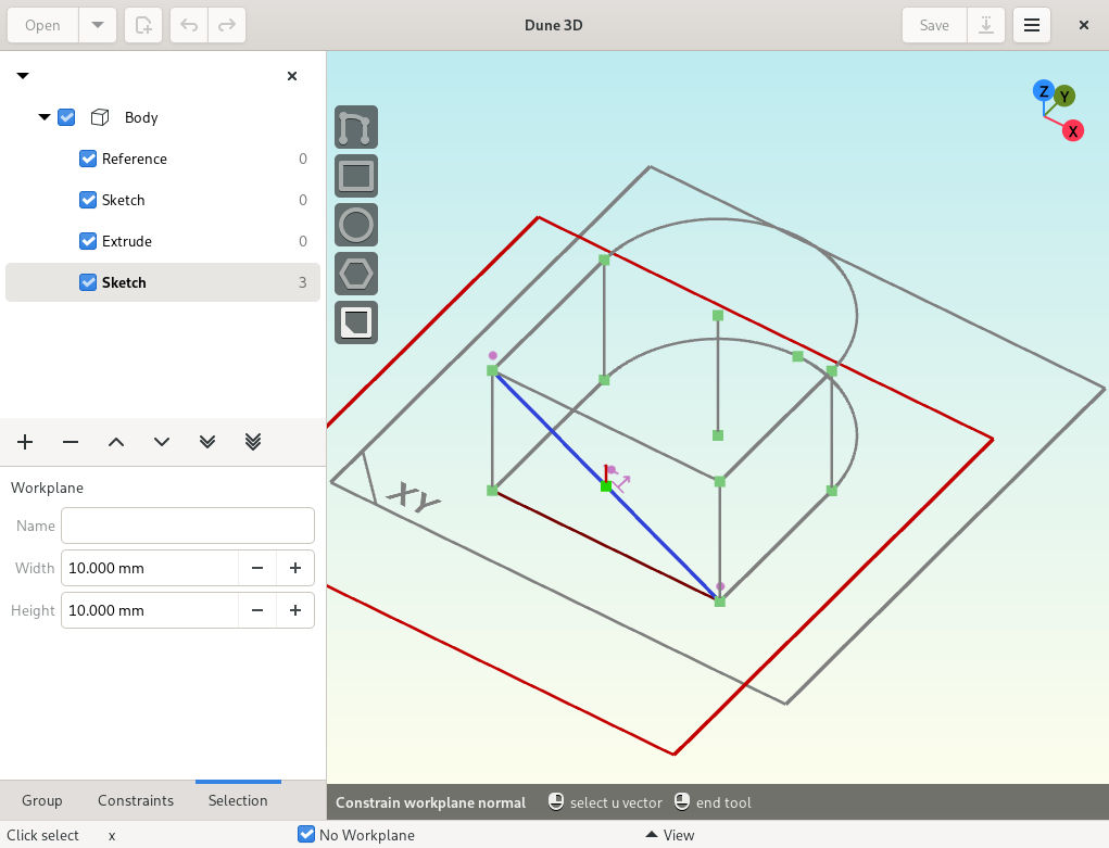
The “Constrain workplane normal” tool requires to click on the the line which corresponds to the workplane’s horizontal direction followed by a second line to define the plane.
The workplane’s normal will be perpendicular to both of the selected lines.
Note
If you get the error “please click on a line from a previous group” its because the reference lines can not be in the current sketch, you forgot to create new sketch first.
Make it the sketch’s active workplane by selecting “Set workplane” from its context menu (right-click).
Sketch pocket
With the new workplane in place, proceed with the sketch for the pocket.
Start by drawing a hexagon with the “Draw regular polygon” tool.
Note
If the line drawing and polygon controls are grayed out, select “Set Workplane” in the workplane’s context menu (right-click) to make it the active workplane.

Constrain pocket sketch
To remove all degrees of freedom:
Constrain the construction circle’s diameter
Constrain the bottom line of the hexagon to be horizontal
Constrain the horizontal and vertical distance from the top-left point of the face
with selecting corresponding points and open the context menu (right-click).
The sketch should look like this:

Pocket extrusion
Create new extrusion (+), change its operation to difference and drag its end inwards so it looks like this:

We want the pocket to end 1mm before the beginning of the semi-circle of the outer part.


Chamfer
Add a chamfer on the top surface.

Note
The chamfer group automatically applies the chamfer to tangent edges.

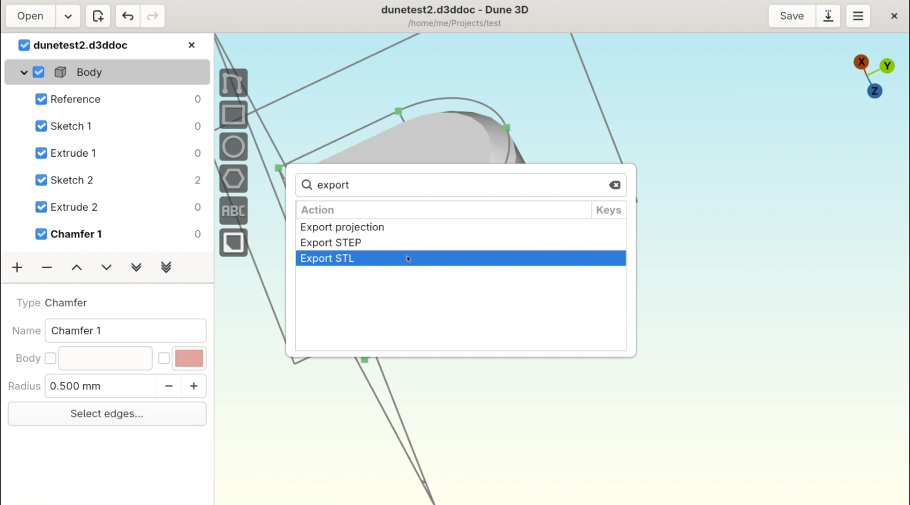
Export